Attacker Community DEF CON 26 Badge
I’ve spent an unhealthy amount of time over the past 6 months or so participating in the craze that is #badgelife. This year, I built badges for my Security Research Group/CTF Team: Attacker Community. (Because community is important when you’re attacking things.) Like last year, all of my badges were designed, assembled, and programmed by me. There are 24 badges this year, each featuring 8 characters of 14-segment display goodness and bluetooth connectivity. I may not be one of the big names in #badgelife, but if you just make some badges for your friends, there’s a lot less pressure in case something comes up.
- TOC {:toc}
![]() {:.center}
{:.center}
Concept
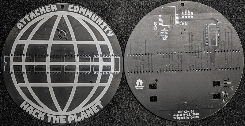
I spent a lot of time kicking around ideas for the badge this year. While I built my DEF CON 25 badge in secret (because I wanted to surprise people with them), this year I solicited ideas from my group. Eventually someone suggested a “Hack the Planet” globe with a display on it, and I ran with it.
The LED displays are intended to throw back to the ’80s, fitting with the DEF CON theme of 1983, but the microcontroller features integrated Bluetooth, bringing it to 2018. The artwork is matte black solder mask with white silk screen (because apparently I don’t know how to do color) and all but one of the badges has classic red LEDs.
Design
I knew from the get go that I wanted to include Bluetooth functionality on the badge. Given the availability of powerful microcontrollers with built-in Bluetooth, it seemed obvious that an integrated solution would be the best option. At first, I looked at the ESP32, but while they are cheap, the power consumption is fairly high, and the documentation isn’t as good as I would have hoped.
Next, I looked at the nRF52 series, and decided I liked them right away. They feature an ARM M4 core, so have an architecture I’m well familiar with, and have a BLE 5 capable radio. Obviously, I didn’t want to build my own antenna and matching section, so I started looking for a module as a solution. At first, I looked at the Rigado modules, but they were a little bit more than I wanted to use for a small badge run (personally financed), so I was happy when I found the somewhat cheaper Fanstel BT832 series. I ended up going with the BT832A, which is based on the nRF52810, a lower flash/lower RAM variant of the popular nRF52832.
Prototyping
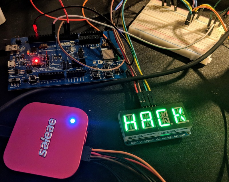
I bought a Fanstel BT832 dev board and some 14 segment displays. I started with the dev board and an Adafruit 14-segment LED backpack. This allowed me to get some experience with the nRF52 SDK, and make sure the general concept was sound without sending out for a custom PCB.
![]() {:.center}
{:.center}
In preparing for the first prototype, I looked for an appropriate LED driver for the 120 LED segments on the 8 characters (organized as the 8 common groups of 15 LEDs). A typical way to drive these is by rapidly pulsing through the common pins (common anode in this case) and as each common pin is activated, the driver outputs the 15 signals for the various LEDs. Surprisingly, I found very little in the way of an easy to use driver, except for the Holtek HT16K33 used in the Adafruit backpack.
There were two problems with the Holtek chip, however. First, it’s relatively hard to obtain – it can’t be purchased on Digikey, Mouser, Jameco, or Arrow. The only source I could find was AliExpress, which is always a dicey proposition. Even at best, it often takes several weeks to receive the product. At worst, it never shows up, or the product is not what was advertised.
Secondly, the HT16K33 is a chip designed for 5V operation, with a specified range of 4.5-5.5V. My badge design was targeting a 3V supply. I began by testing my protoboard prototype and seeing how low I could drive the prototype and still have everything working. I was pleasantly surprised (and somewhat amazed) to see that the HT16K33 kept working until the voltage had dropped so low that the LEDs stopped lighting due to their forward voltage (~1.8V). Unfortunately, I had no way to know if that was specific to this one chip or if all of the chips would behave similarly. Still, since I had this working, I pressed onward with my design.
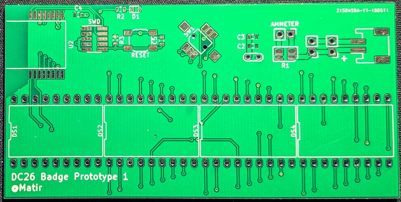
I designed a full-scale prototype with the NRF module, the 4 displays (2 characters each), the HT16K33 LED driver, and a number of test points to measure voltage, current, etc. I sent the board design off to JLCPCB. (I’d heard good things, figured it was a good opportunity to try them out.)
 {:.center}
About two days later, I realized I had made a terrible mistake in the design: while I had properly laid out the pinout of the LED displays, I had neglected to take into account the physical overhang of the displays beyond the pins. There’s no way all 4 displays would physically fit on the board! I debated immediately redoing the board, but decided to try to “make it work” in the interests of time. I ended up attaching the displays using segments of hookup wires. It wasn’t the best option, but it got the job done.
Final Design
The final electronic design ended up with:
- BT832A module containing nRF52810 SoC
- HT16K33 LED Display Driver (8x16 memory mapped)
- 4 dual 14-segment LED displays
- 2xAAA battery holder providing 3V nominal
- A 5-way joystick for user control
There’s a handful of other passives (both bulk and bypass capacitance, an indicator LED for BLE status, etc.). Internal pull-ups were adequate for the I2C lines to the HT16K33. In production firmware, the reset pin is disabled to avoid spurious resets. On the prototype board, there’s a reset button with an RC circuit for debounce.
Assembly
 {:.center}
I had the final boards produced at Elecrow (because they don’t print order numbers on the boards and offered matte black solder mask). After I received the PCBs, I assembled a quick test badge (#0x01) and was pleasantly surprised to find that it actually worked!
Then I had to assemble the 24 other boards. By hand. Without a reflow even. It turned out that working in batches of 4-5 boards at a time was the most efficient way I could.
I placed all the SMD components (except the battery holder) on the back of the board and used my hot air gun to reflow the SMD components. Placing the BLE module and get its castellations aligned was, by far, the hardest part of this stage. (Though don’t underestimate trying to solder 0603 components with a hot air gun – they really like to blow around from the force of the wind.)
Next, I inserted the 4 displays from the front, and hand-soldered each of the 72 joints (that’s 1800 total joints on the 25 badges). I added the battery holder and joystick and soldered those in place. At this point, each badge should be functional, but it’s hard to know for sure since there was no software on them yet to make them do anything.
Firmware
Unlike when working with most microcontrollers, where using the vendor’s SDK is optional (you can directly interact with the various control and I/O registers), when working with an embedded BLE controller, you really need to use the SDK. In the case of the nRF52 series, the SDK is necessary to talk to the “SoftDevice” that runs the BLE stack.
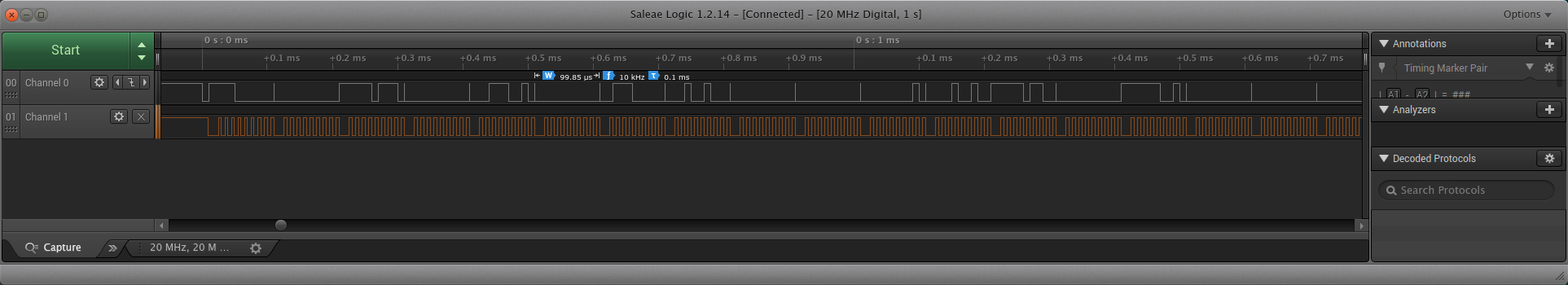
One thing worth noting is that, due to the tight timing constraints of the BLE stack, the highest priority interrupts are reserved for it. Consequently, depending on very tight timing can be difficult. I discovered this during the first prototype and had to debug it using the Saleae logic analyzer. (These logic analyzers are the Swiss Army Knife of digital domain signals.)
 {:.center}
In particular, the Saleae logic analyzer helped me discover that I was occasionally transmitting the completely wrong bytes to the HT16K33 display driver. It turns out that pointer math is hard, and you should be really careful about that. Amazingly, I managed not to corrupt memory (or at least, not badly enough to completely break things) but given that the firmware is written in low-level C, there’s a fair bit of pointer weirdness going on. Eventually, though, I got it right.
 {:.center}
The minimal firmware I built was just enough to display a single message on the displays, and allow turning the displays on/off. This was the proof of concept that ran on the breadboard design.
I used the prototype board to begin building out the more extensive firmware. This included multiple messages and display styles (scrolling, etc.), variable brightness, and the Bluetooth setup to allow customizing messages and other settings.
One of the biggest firmware challenges was getting the BluetoothLE Secure Connections (LESC) feature enabled. As of the time I was working on it, the SDK would not even compile with LESC enabled on the nRF52810. It’s clearly not an oft-used (or tested at Nordic) feature. The documentation also left a lot to be desired in terms of understanding the requirements for the LESC feature.
Programming & Testing
Each badge has 4 round contact points (test points) for the voltage supply (VCC), ground (GND), and Single Wire Debug Clock (SWDCLK) and Data (SWDIO) lines. These four lines allow me to program the badges using 4 spring-loaded contacts and a USB to SWD adapter.
Because of the hand-assembled nature of the badges, I really needed to find a way to test the electrical connections. With 16 connections on the BLE module, 72 LED display connections, 28 pins on the HT16K33, and 6 contacts on the joystick, there were plenty of places for things to go wrong even after a visual inspection. Consequently, I wrote a mode into the firmware that tests all of the LEDs as well as the joystick. Given the overall design, this tested nearly all of the relevant electrical connections.
Each badge can be “factory reset”, which triggers the self-test again, as well as resetting all the messages to the default, and clearing any Bluetooth pairings. This was necessary in case I needed to re-run the tests or modify the format of the data stored in flash.
Android App
Obviously, if you’re going to use something that has Bluetooth, you need a way to talk to it. I wanted people to be able to configure the messages to be displayed on their badge, allowing for personalization, and I thought it would be a little different than other badges. So I figured I’d make a quick Android app – how hard could it be?
It turns out that if you haven’t done any Java in about 10 years, it gets much harder. But eventually I got things working. There was a lot of back and forth between the Android App and the firmware in order to get the pairing working, the communications working the way I want to, etc.
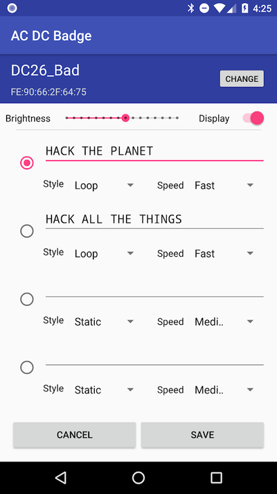 {:.center}
Eventually, the Android App came together and was actually my first published Android application. Hopefully it’ll actually work in the field.
Lessons Learned
- Do not trust SDK documentation. It will be wrong in some way. Be prepared to read the SDK source code in order to understand how the SDK really works.
- If you are using digital signals between chips on your PCB, get a logic analyzer. It will make your life so much easier if you can see what your chips are actually doing.
- Put test points for all your signals on your prototype board. Why force yourself to try to clip to TSSOP leads when you could have put proper test points on the board?
- If you estimate how long something will take, you will be wrong. It will take longer.
- If you want to make more than a handful of badges, don’t plan on assembling them by hand. It’s repetitive, and repairing your errors will burn your time like no other.
Conclusion
![]() {:.center}
{:.center}
This has been a fun build. It’s my first time developing for Android, first time developing with Bluetooth, first time with this chipset. It’s been a blast, but it’s been a ton of work.
If you want to see all the details, I’ve open sourced it all. It’s all there: the firmware, the KiCad files, the Android App, and it’s all under the MIT license.
Other Adventures in #badgelife
I’d be remiss if I didn’t mention that this wasn’t the only badge I worked on this year. My company hosts an amazing invite-only lounge during DEF CON each year, and this year we have an electronic badge. A team of 3 of us put this one together, so hats off to @twitchyliquid64 and claymore. The badges interact via IR when our hosts (Googlers) and guests interact. I’m really excited to see how they work out at the event.