The Wio Terminal - Integrated Making?
Please note: Seeed Technology Co Ltd (aka Seeed Studio) provided the Wio Terminal for use in this post. I have not been compensated in any other way for this post. If you’re not familiar with Seeed, there’s an introduction to their offerings at the bottom.
While the Arduino and similar development boards have been available for more than a decade, there has been a trend as of late to abstract away the hardware aspects and allow users to focus on it at a higher level. First, we had standard interfaces to which you could attach “shields”, “hats”, “featherwings”, or other add-on boards. Then came options like Seeed’s Grove System and SparkFun’s Qwiic, which were both I2C busses exposed over a standardized connector, allowing the connection of many peripherals at once. There’s also been an expansion into development boards with built-in sensors and outputs, like Adafruit’s Circuit Playground. The Wio Terminal is the most sophisticated and complete incarnation of this trend that I’ve seen thus far.
 {:.center}
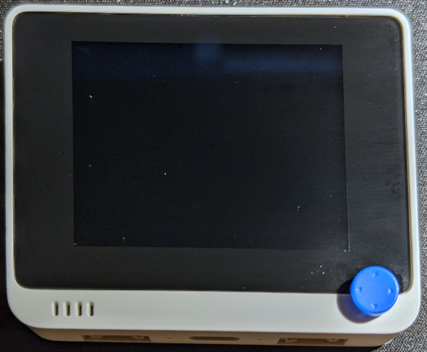
The first thing you’ll notice about the Wio Terminal is it’s 2.4" LCD screen, but under the hood, it’s powered by an Atmel SAMD51 Microcontoller (120 MHz ARM Cortex M4F) paired with a Realtek RTL8720DN for WiFi and BLE. It has a 5 way switch, multiple buttons, and a Micro-SD card slot. Embedded peripherals include an accelerometer, microphone, speaker, and light sensor. I/O is available via a Raspberry Pi compatible 40 pin header, 2 Grove interfaces, and USB type C.
When Seeed Technology offered me a Wio to take a look, I thought it would be a great idea. I’m curious both what can be done as a standalone device and what can be done with attached hardware. I’m also excited that it’s completely open source hardware.
 {:.center}
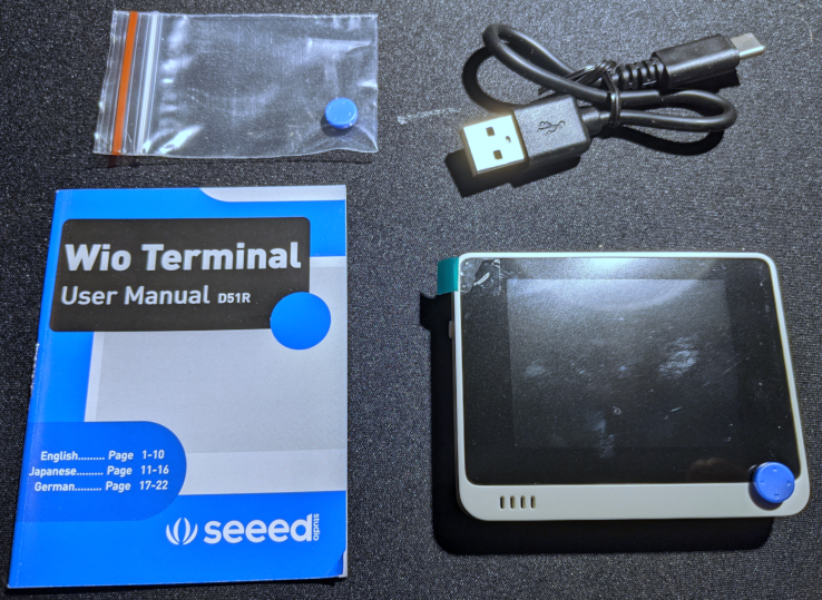
Inside the box, you find the Wio Terminal itself, with a plastic peel to protect the screen in shipping (it was also inside a small plastic bag, removed for this photo), a user manual, a short USB-C cable, and a spare 5-way switch hat. The manual is very brief and beyond covering where to put the power cord, I’d suggest to only use the online documentation instead.
The documentation on Seeed’s Wiki is really quite good. There is some setup necessary to get ready to use the Wio Terminal with the Arduino IDE, but it’s quite straightforward. I first uploaded the standard Arduino “blink” sketch just to verify that I had everything working correctly. This did, in fact, blink the blue status LED next to the USB-C port on the Wio Terminal.
Build Quality
Overall, I thought the build quality was quite good for something at this price point. The injection molded parts seem to be quite well made, and the screen is acceptable for a 320x240 resolution TFT. There’s significant backlight bleed, but that’s very common at this price point.
 {:.center}
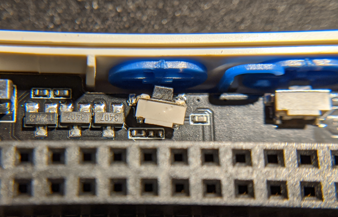
Unfortunately, I had one issue where one of the buttons broke off the PCB the first time I pushed it. I’ve reached out to Seeed to and they indicated this isn’t an issue they’ve seen in their testing, so it was likely either shipping damage or a one-off case. Since the other two buttons are solid, I’ll chalk this up to bad luck.
 {:.center}
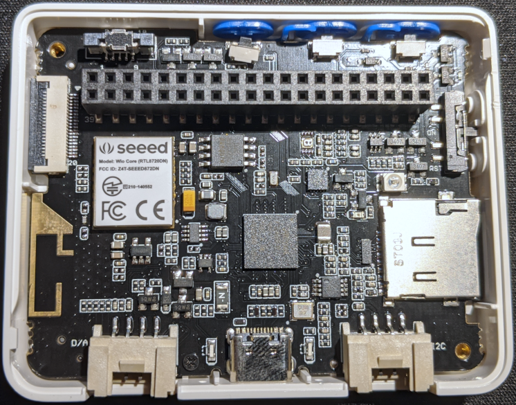
Inside we can see what makes it take. The SAMD51 microcontroller is dead center, and the small metal cover with the “seeed” sticker contains the WiFi chipset. The microSD slot is bottom right, USB C center bottom (flanked by Grove connectors on either side), the 40 pin header is all along the top.
It’s extremely light weight in the hand, but not to the point of feeling excessively cheap, just light. Since all components are on a single PCB, this is not surprising.
Building a WiFi Scanner
I decided to build a little WiFi scanner to use the WiFi chip, display the list of found networks on the screen, and then allow moving through the list by way of the 5-way joystick. This would get me a chance to play with most of the major functionality. (I have not used the IR led or audio functionality.)
This would probably be a lot more interesting with the optional battery as a portable “War Walking” device.
WiFi Setup
In order to use the WiFi functionality of the Wio Terminal, you must upload the latest firmware to the WiFi chipset. It’s well documented on their wiki, but basically it boils down to flashing a special Arduino sketch, then running a tool that uploads the firmware. The Arduino sketch appears to make the main processor just bridge traffic between the serial port on USB and the serial port on the RTL8720.
I started by flashing their WiFi scanning sketch and noticed that it was
inconsistently showing whether given networks were encrypted. Additionally,
examining the results of WiFi.encryptionType for a network seemed to provide
non-sensical values, varying quite a bit. I soon discovered a bug in their
atUnified library where it did not copy the encryption field from the scan
results, so I was just getting noise off the stack. I’ve submitted a pull
request to
their library to fix the bug.
From digging into the firmware, I discovered that the RTL8720D firmware you load
provides essentially the same command set as offered by the ESP32/ESP8266 in
AT mode, which is a pretty clever way to allow a lot of existing Arduino code
to be ported relatively easily. (And explains why libraries with esp in the
name are needed for WiFi support on the Wio Terminal.)
Integrating LCD
The Wio Terminal’s LCD is compatible with the TFT_eSPI library. Drawing to the screen is quite easy, although like with any other SPI-based display, you will not be getting super high framerates. I started rendering the WiFi scans on the display with only about 20 minutes of coding time, most of which was figuring out how to draw a box containing text in the middle of the screen (which turns out to be trivial).
Final Project
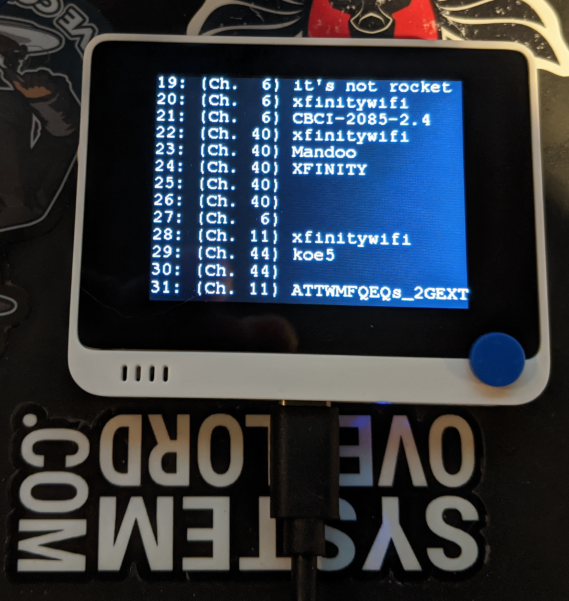 {:.center}
Code for the final scanner, shown above:
  1#include "AtWiFi.h"
  2#include "TFT_eSPI.h"
  3#include "Free_Fonts.h"
  4
  5TFT_eSPI tft;
  6int list_display_offset = 0;
  7int rescan = 1;
  8int refresh = 1;
  9
 10#define SCREEN_Y 240
 11#define SCREEN_X 320
 12
 13#define Serial_printf(...) do {sprintf(buf, __VA_ARGS__); Serial.print(buf);}while(0)
 14
 15void doOneScan();
 16void handleBtnB();
 17void handleStickDown();
 18void handleStickUp();
 19void drawOnScreen();
 20void drawMessageBox(char *msg);
 21
 22void setup() {
 23  char buf[128];
 24  Serial.begin(115200);
 25  while (!Serial); // Wait for Serial to be ready
 26
 27  // Set WiFi to station mode and disconnect from an AP if it was previously connected
 28  WiFi.mode(WIFI_STA);
 29  WiFi.disconnect();
 30  delay(100);
 31
 32  // Setup tft
 33  tft.begin();
 34  tft.setRotation(3);
 35  tft.setFreeFont(FM9);
 36  tft.fillScreen(TFT_BLACK);
 37  digitalWrite(LCD_BACKLIGHT, HIGH);
 38
 39  // Attach interrupts
 40  pinMode(WIO_KEY_A, INPUT_PULLUP);
 41  attachInterrupt(digitalPinToInterrupt(WIO_KEY_B), handleBtnB, FALLING);
 42  pinMode(WIO_5S_UP, INPUT_PULLUP);
 43  attachInterrupt(digitalPinToInterrupt(WIO_5S_UP), handleStickUp, FALLING);
 44  pinMode(WIO_5S_DOWN, INPUT_PULLUP);
 45  attachInterrupt(digitalPinToInterrupt(WIO_5S_DOWN), handleStickDown, FALLING);
 46
 47  Serial.println("Setup done");
 48  Serial_printf("WIFI_AUTH_OPEN: %d\n", WIFI_AUTH_OPEN);
 49  Serial_printf("WIFI_AUTH_WEP: %d\n", WIFI_AUTH_WEP);
 50  Serial_printf("WIFI_AUTH_WPA_PSK: %d\n", WIFI_AUTH_WPA_PSK);
 51  Serial_printf("WIFI_AUTH_WPA2_PSK: %d\n", WIFI_AUTH_WPA2_PSK);
 52  Serial_printf("WIFI_AUTH_WPA_WPA2_PSK: %d\n", WIFI_AUTH_WPA_WPA2_PSK);
 53  Serial_printf("WIFI_AUTH_WPA2_ENTERPRISE: %d\n", WIFI_AUTH_WPA2_ENTERPRISE);
 54}
 55
 56void loop() {
 57  if (rescan) {
 58    doOneScan();
 59    refresh = 1;
 60  }
 61  if (refresh) {
 62    refresh = 0;
 63    drawOnScreen();
 64  }
 65  delay(10);
 66}
 67
 68void handleBtnB() {
 69  rescan = 1;
 70}
 71
 72void handleStickDown() {
 73  list_display_offset++;
 74  refresh = 1;
 75}
 76
 77void handleStickUp() {
 78  if (list_display_offset > 0)
 79    list_display_offset--;
 80  refresh = 1;
 81}
 82
 83void drawMessageBox(char *msg) {
 84  int16_t width = tft.textWidth(msg) + 20;
 85  int16_t height = tft.fontHeight() * 2;
 86  // Save the datum so we can restore on exit
 87  uint8_t old_datum = tft.getTextDatum();
 88  tft.setTextDatum(MC_DATUM);
 89
 90  // Draw box outline
 91  int32_t x = (SCREEN_X-width)/2;
 92  int32_t y = (SCREEN_Y-height)/2;
 93  // Draw filled black for the background
 94  tft.fillRect(x, y, width, height, TFT_BLACK);
 95  // Draw red border
 96  tft.drawRect(x, y, width, height, TFT_RED);
 97  // Now fill in the text
 98  tft.drawString(msg, SCREEN_X/2, SCREEN_Y/2);
 99
100  // Restore the old Datum
101  tft.setTextDatum(old_datum);
102}
103
104// Do a single scan
105void doOneScan() {
106  char buf[128];
107  Serial.println("scan start");
108
109  drawMessageBox("Scanning...");
110
111  // WiFi.scanNetworks will return the number of networks found
112  int num_networks = WiFi.scanNetworks();
113  if (num_networks < 0) {
114    Serial.println("Error scanning!");
115    return;
116  }
117  Serial.println("scan done");
118  if (num_networks == 0) {
119    Serial.println("no networks found");
120  } else {
121    Serial.print(num_networks);
122    Serial.println(" networks found");
123    for (int i = 0; i < num_networks; ++i) {
124      sprintf(buf, "%02d: (Ch. %2d) %-16s %s [RSSI: %03d, ENC: %d]\n", i, WiFi.channel(i), WiFi.SSID(i).substring(0, 16).c_str(), WiFi.BSSIDstr(i).c_str(), WiFi.RSSI(i), WiFi.encryptionType(i));
125      Serial.print(buf);
126    }
127  }
128  Serial.println("");
129  rescan = 0;
130}
131
132// Draw all the current results on the screen
133void drawOnScreen() {
134  char buf[128];
135  tft.fillScreen(TFT_BLACK);
136  int n = WiFi.scanComplete();
137  Serial.println("drawOnScreen called");
138  if (n < 0) {
139    Serial.println("Results not available in drawOnScreen!");
140    return;
141  } else if (n == 0) {
142    Serial.println("No scan results!");
143  }
144  if (list_display_offset > n)
145    list_display_offset = n;
146  Serial.print("Starting at offset: ");
147  Serial.println(list_display_offset);
148  int16_t line_height = tft.fontHeight();
149  for (int i = 0; i < n; ++i) {
150    sprintf(buf, "%02d: (Ch. %2d) %-16s %s [RSSI: %03d, ENC: %d]", i, WiFi.channel(i), WiFi.SSID(i).substring(0, 16).c_str(), WiFi.BSSIDstr(i).c_str(), WiFi.RSSI(i), WiFi.encryptionType(i));
151    if (i < list_display_offset)
152      continue;
153    int start_y = line_height * (i - list_display_offset);
154    if (start_y >= SCREEN_Y)
155      break;
156    tft.drawString(buf, 0, start_y);
157  }
158  Serial.println("drawOnScreen done");
159}
Little Quirks
There were a couple of things I found a bit quirky or unusual while working with the Wio Terminal. None are show-stoppers, just things you have to work around. Note that my expectation of the orientation of the terminal is screen facing you, 5-way switch in lower right corner, as is also shown in most of their marketing materials.
The buttons on top are ordered from right to left. So button “A” is the furthest right when looking at it head on. This is backwards of my expectation, and neither the included manual nor the wiki page on configurable buttons explains otherwise.
For the screen to be “upright” in the same orientation as described above,
you need to call tft.setRotation(3);. Again, not a big deal, just something
to be aware of as you develop with the Wio Terminal.
Other Use Cases
In addition to the standalone mode, you can also use it on top of a Raspberry Pi. The two communicate over I2C and other pins remain unused (though it will be difficult to break it out). This could be a fascinating approach to allow the SAMD51 in the Wio Terminal to do hard real time aspects while the Raspberry Pi could run a webserver, longer-term computation, or other things requiring more processing power.
In addition to being programmed via the standard Arduino IDE, it also supports MicroPython to allow development in Python, and the 4MB SPI flash provides adequate space for these programs.
Conclusion
Overall, I think the Wio Terminal is a good value at it’s $30 USD price point. I strongly suggest getting the $10 battery addon (which I didn’t have a chance to try out, but looks useful), as portable projects are where I would really expect this to shine. (Of course, you can just use a USB-C cable to a battery pack if you prefer, but then you won’t have the sleek look of the combined interfaces.)
The 40 pin interface on the back and the Grove connectors will allow connection to a large number of external devices without needing to solder, use breadboards, etc. With Grove, it’s pretty easy to connect a device without risking connecting it in a wrong way.
It’s great that it’s open source hardware and the software libraries are also under various open source licenses. While it would not be a trivial undertaking to make your own version, it really gives you a chance to see and understand how the device works (and, in my case, find and fix a bug in an underlying library). If you look at the schematic, you’ll notice a previous revision had a secure element (the ATECC508) on the board, but unfortunately, that has been removed. Not a big deal, but it would’ve been fun to play with.
If you want to do more with Arduino, and particularly if a screen is in your desire, I can solidly recommend the Wio Terminal. It won’t replace everything else in the Arduino ecosystem (there are cheaper or more specialized options), but if you want something to just let you start programming and gives you I/O and a screen, the Wio Terminal is a great choice.
About Seeed
Seeed provided the following snippet to describe their offerings:
About Seeed Studio{:rel=‘nofollow’} Seeed is the IoT hardware enabler providing services over 10 years that empower makers to realize their projects and products. Seeed offers a wide array of hardware platforms and sensor modules ready to be integrated with existing IoT platforms and one-stop PCB fabrication{:rel=‘nofollow’} and PCB assembly service{:rel=‘nofollow’}. Seeed Studio provides a wide selection of electronic parts including Arduino{:rel=‘nofollow’}, Raspberry Pi{:rel=‘nofollow’} and many different development board platforms Especially the Grove System{:rel=‘nofollow’} help engineers and makers to avoid jumper wires problems. Seeed Studio has developed more than 280 Grove modules covering a wide range of applications that can fulfill a variety of needs.