A Cheap and Compact Bench Power Supply
I wanted a bench power supply for powering small projects and devices I’m testing. I ended up with a DIY approach for around $30 and am very happy with the outcome. It’s a simple project that almost anyone can do and is a great introductory power supply for any home lab.
I had a few requirements when I set out:
- Variable voltage (up to ~12V)
- Current limiting (to protect against stupid mistakes)
- Small footprint (my electronics work area is only about 8 square feet)
- Relatively cheap
Initially, I considered buying an off the shelf bench power supply, but most of those are either very expensive, very large, or both. I also toyed with the idea of an ATX power supply as a bench power supply, but those don’t offer current limiting (and are capable of delivering enough current to destroy any project I’m careless with).
I had seen a few DC-DC buck converter modules floating around, but most had pretty bad reviews, until the Ruidong DPS series came out. These have quickly become quite popular modules, with support for up to 50V at 5A – a 250W power supply! Because of the buck topology, they require a DC input at a higher voltage than the output, but that’s easily provided with another power supply. In my case, I decided to use cheap power supplies from electronic devices (commonly called “wall warts”). (I’m actually reusing one from an old router.)
I’m far from the first to do such a project, but I still wanted to share as well as describe what I’d like to do in the future.
This particular unit consists of a DPS3005 that I got for about $25 from AliExpress. (The DPS5005 is now available on Amazon with Prime. Had that been the case at the time I built this, I likely would have gone with that option.)
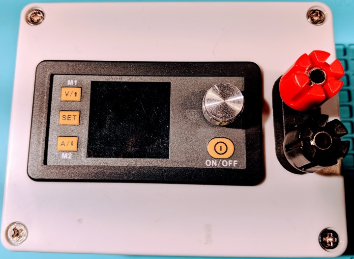
I placed the power supply in a plastic enclosure and added a barrel jack for input power, and added 5-way binding posts for the output. This allows me to connect banana plugs, breadboard leads, or spade lugs to the power supply.
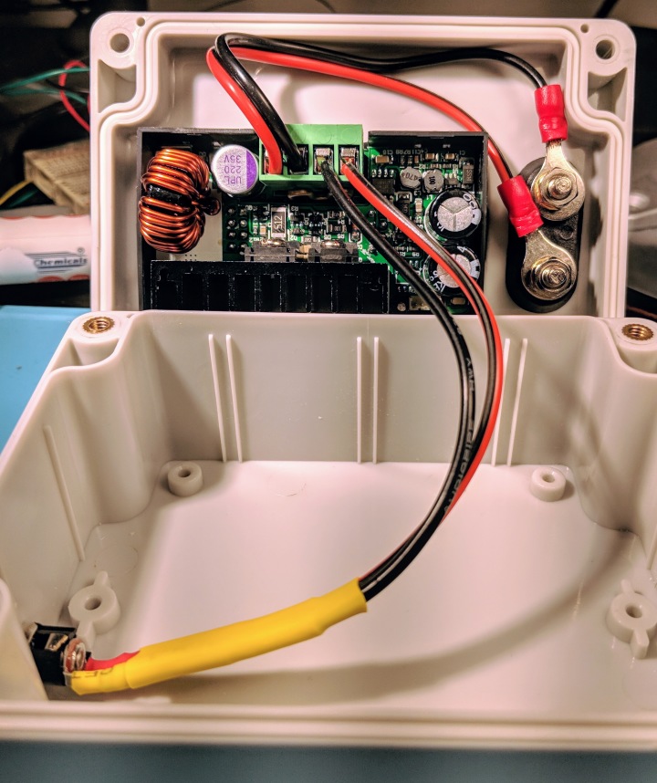
Internally, I connected the parts with some 18 AWG red/black zip cord using crimped ring connectors on the binding posts, the screw terminals on the power supply, and solder on the barrel jack. Where possible, the connections were covered with heat shrink tubing.
I used this power supply in developing my Christmas Ornament, and it worked a treat. It allowed me to simulate behavior at lower battery voltages (though note that it is not a battery replacement – it does not simulate the internal resistance of a run down battery) and figure out how long my ornament was likely to run, and how bright it would be as the battery ran down.
I’ve also used it to power a few embedded devices that I’ve been using for security research, and I think it would make a great tool for voltage glitching in the future. (In fact, I saw Dr. Dmitry Nedospasov demonstrate a voltage glitching attack using a similar module at hardwaresecurity.training.)
In the future, I’d like to build a larger version with an internal AC to DC power supply (maybe a repurposed ATX supply) and either two or three of the DPS power modules to provide output. Note that, due to the single AC to DC supply, they would not be isolated channels – both would have the same ground reference, so it would not be possible to reference them to each other. For most use cases, this wouldn’t be a problem, and both channels would be isolated from mains earth if an isolated switching supply is used as the first stage power supply.